
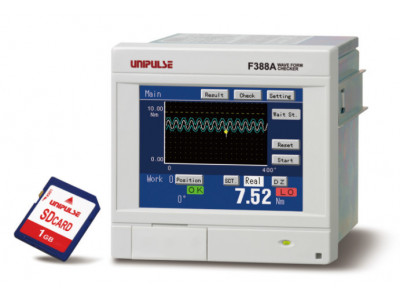

Product outline
F388A is a wave form checker integrated with a voltage / current output type sensor that can display physical quantities such as pressure, load and torque in waveforms. It is able to visually capture in waveforms the fluctuations in physical quantities which are difficult to capture by only numerical values. With a 4000 times per second for high-speed processing, it is also ideal for narrow value fluctuations and comes equipped with a HI/LO limit comparison function, various hold functions and judgment function. F388A can be used in a wide-range of applications such as in control systems used in production control, automatic devices or testers.
LCD touch panel
Setting operation can be effortlessly performed by a direct touch on touch panel.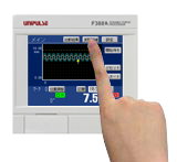
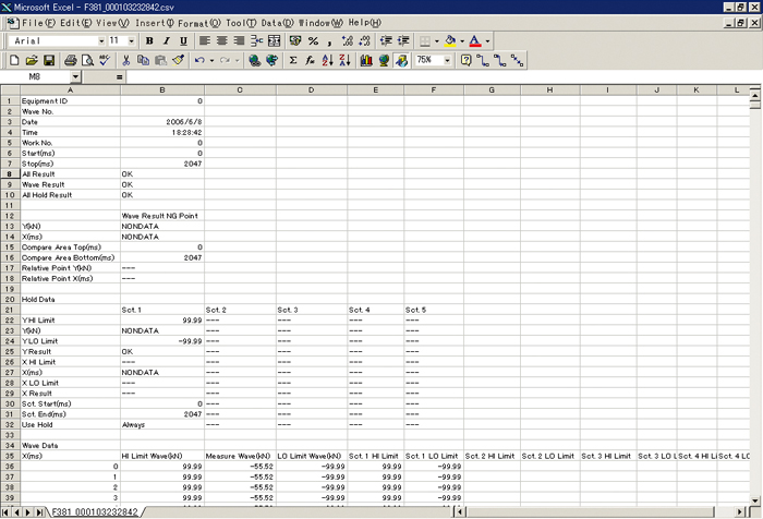
Saves measurement data in an SD card
Measurement data and set values can be logged (recorded) in the SD card. Such data can be retained as 100% recorded quality data or be used when setting up equipment or when performing cause analysis or improvement of problems. The data can be easily converted to CSV format and is therefore easily edited in Microsoft Excel or the like.
Plus common/ minus common shared sink type/ source type selectable
Its input type is combined-use plus common / minus common while its output type is selectable between sink type and source type. It can be connected to various types of external equipment such as PLCs.
4000 times/sec. high-speed processing
F388A is installed with a high-speed A/D converter and high-speed CPU that can process sensor signal input at 4000 times/sec. with this, fluctuations in narrow values will not be overlooked.
Wide array of interfaces
F388A provides a wide array of interfaces to give flexibility in system networking. As starters, there is the Ethernet and the proven RS-232C that can provide a direct link to site PLCs such as the OMRON DeviceNet or the MITSUBISHI CC-Link without the need for any bridging devices.
Comparison & hold function by waveform display
These functions are used to judge the acceptability of measurement waveforms. Depending on type of applications, Waveform Comparison Function and Multi Hold Function can be jointly utilized for judgment.
Waveform comparison function
This function compares the actually measurement waveform against the setup Hi/Lo limit waveforms and will give out an NG judgment when any of the point exceeded the set Hi/Lo limit waveforms. As it compares the measurement waveform in overall, accurate judgment can be made even in applications that are unable to narrow down its judgment.
Multi hold function
After the measuring area is divided, judgment can be carried out while type of hold (sample, peak, valley, P-P, max, min, inflection point) is interchanged at will. It is capable in specifying Hi limit value, Lo limit value and type of hold at each interval.
Comparison results display
The comparison results of Waveform Comparison Function and Multi Hold Function can be verified on the display.【Result(List)】(An individual display) and 【Result(Single)】(a list display) to selection is possible. (Latest 40 data)
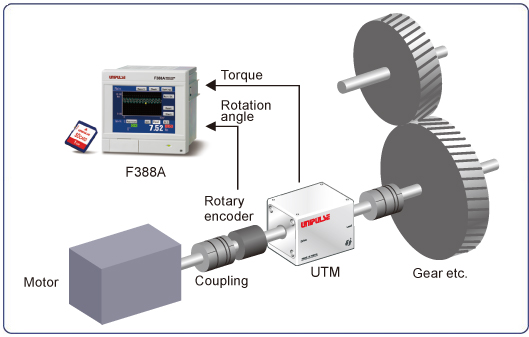
Example of use combined with torque meter UTM
Specifications
| Sensor input for voltage/ current | |
| Voltage input | -10 to +10V Input impedance: 1MΩ or more |
|---|---|
| Current input | -20 to +20mA Input resistance: Approx. 250Ω |
| Accuracy | Non-linearity: 0within 0.02%/FS±1digit (at a 10V or 20mA input) Zero drift: within 0.2mV/℃ RTI or within 0.4μA/℃ RTI Gain drift: within 0.01%/℃ |
| Analog filter | Low pass filter (-6dB/oct.) Selectable at 10, 30, 100, 300Hz |
| A/D converter | Speed: 4000 times/sec. Resolution: 24bit (binary) Effective resolution: Approx. 1/30000 to 10V or 20mA input |
| Analog voltage output | Output level: Approx. 0.6V per 1V input or approx. 0.15V per 1mA input Load resistance: 2KΩ or more |
| Sensor input pulse input (open collector) | |
| Maximum input frequency | 50kHz |
|---|---|
| Internal counting range | Approx. 1,000,000 |
| Adaptable sensor | Output: Incremental type 2-phase output (A/B signal output) Also capable of single-phase output (A-phase input used. All pulses are counted as in the plus direction.) Output stage circuit specification: open collector (NPN type, Vceo=30V or more, Ic=30mA or more) |
| Display section | |
| Display unit | TFT color LCD module Display area: 71(W)×53(H) mm Dot structure: 320×240dot |
|---|---|
| Indicated value | Load: -9999 to +9999 Displacement: -9999 to +32000 Decimal point: The decimal place is to be input together with a value at the time of calibration. 0.000, 0.00, 0.0, 0 |
| Number of display times | Fixed at 3 times/sec. |
| Setting section | |
| Setting method | Setting by analog type touch panel operation. |
|---|---|
| Preservation of set values | NOV RAM (nonvolatile RAM), Lithium-battery-backed-up C-MOS RAM |
| I/O section | |
| Input signals | 16 points Input type: plus common / minus common shared To connect a transistor, connect NPN output type (sink type) for plus common and PNP output type (source type) for minus common. ON voltage: 12V or more, OFF voltage: 3V or less, 24VAt 24V load: approx. 5mA Isolation: photocoupler |
|---|---|
| Output signals | 16 points Output type: sink type/ source type selectable. (Source type is optional [ISC].) Output transistor ON at signal ON. To connect an input unit like a PLC, connect plus common for sink type, and minus common for source type. Rated voltage: 30V, Rated current: 30mA Isolation:photocoupler |
| Interface | |
| RS-232C communication interface | Start/stop system Baud rate: 1200bps to 38400 bps All parameters can be read and written. All comparison waveforms can be read and written. Measurement waveforms and judgment points can be read. |
|---|---|
| Option ( Only one interface option can be installed.) | |
| SD card slot [SDC] | All parameters can be preserved and reconstructed. All comparison waveforms can be preserved and reconstructed. Measurement waveforms and judgment points can automatically be preserved. * An SD card of 1GB is attached. Approx. 80 waveforms can be memorize by 1MB. |
|---|---|
| I/O sourrce boad [ISC] | Output type: sourrce type To connect an input unit like a PLC, connect minus common. |
| DeviceNet interface [ODN] | Connectable with DeviceNet-compliant OMRON CompoBus/D seamlessly. All parameters can be read and written. All comparison waveforms can be read and written. Measurement waveforms and judgment points can be read. |
| CC-Link interface [CCL] | Directly linkable with a Mitsubishi (multipurpose) sequencer. All parameters can be read and written. Judgment points can be read. |
| Ethernet interface [ETN] | All parameters can be read and written. Measurement waveforms and judgment points can be read. |
| General performance | |
| Power supply voltage | DC24V (±15%) |
|---|---|
| Power consumption | 20W max |
| Inrush current (Typ) | 2A, 10msec (at ordinary temperature, cold-start) |
| Operating conditions | Operating temperature range: -10 to +40℃, Storage temperature range: -20 to +60℃ Humidity: 85%RH or less (non-condensing) |
| Dimensions | 96(W)×96(H)×117.3(D) mm (Projections excluded) Panel-cut dimensions: 92×92 (+1-0) mm |
| Weight | Approx. 1.0kg |
Option
| Model | |
| ISC | I/O Source board |
|---|---|
| SDC | SD Card slot (An SD card of 1GB is attached.) |
| ODN | DeviceNet interface |
| CCL | CC-Link interface |
| ETN | Ethernet interface |
Optional accessories
| Model | |
| DTC1 | Case for F388A (with AC power supply) |
|---|---|
| SD1G | 1GByte card |
| SD2G | 2GByte card |
| CA81-232X | miniDIN-D-Sub9p cross cable |
| CN52 | FCN series I/O connector (with cover) |
| CN57 | FCN series I/O connector (with diagonal cover) |
| CN60 | Circular DIN 8p connector for RS-232C |
| CN71 | CC-Link connector |
| CN81 | Analog I/O connector terminal |
| CND01 | DeviceNet connector |
| GMP96×96 | Rubber packing |


